Fast Robots (MAE 4190) Assignments
Apurva Hanwadikar
Contents
prelab
Debugging
The plan is to have the robot run for some set amount of time and shut off after that time has passed (in this case 5 seconds). I implemented three new commands over BLE: hard stop, get data, and pid tuning. Triggering either a hard stop or timing out the loop will stop the motors and then send over the sensor and timing data as well as the PID tuning parameters which have been stored on the Artemis as the robot ran. All BLE commands are sent before and after the PID loop runs the motors to prevent delays from that. All Serial print messages were removed at the end to mitigate delays from that.
labtasks
Position Control
I started out with just proportional control initially to get an idea of what is physically reasonable for the car.
High proportional gain values will cause a lot of oscillation because it causes the car to adjust at high speeds which means the controller will constantly be adjusting to large shifts back and forth and create oscillation. Low proportional gain values are technically safer but that would slow down the system substantially to the point where the robot won’t be moving fast or interestingly enough to do the tricks we require later.
If the robot starts at 3m away from the wall, the initial error is 2700 mm. That is going to saturate immediately unless Kp is small because the upper limit on u is 255 (max PWM). So a good starting point is 0.05-0.15 as that’ll get us in the range of the higher speeds of the robot.
I also set
distanceSensor.setTimingBudgetInMs(20)
to 20Hz. This means that the data update rate is much faster so the sensor is more responsive which is ideal at high speeds. At lower data update speeds the car can travel quite a lot between each reading so it causes oscillation as the car has to adapt to the latest data after it’s already moved a lot. The tradeoff on this is noisier data but we’re making the car stop at a relatively far enough point from the wall (304 mm) that losing accuracy by a few millimeters is preferrable over jerky car movement. I’m using the long distance mode because I wanted to make sure it had the ability to detect the wall if I placed it far away and my general logic for this lab is to trade off accuracy for more data, regardless of quality.
When I tested closer to the wall I ended up in the deadband of the motor because my error was smaller so my commanded speed was smaller. My car’s deadband is around 40 (at least on the surface I’m working on). So, at the bottom of my PWM calculation code I added deadband compensation to account for it. This means that even if the u value calculated is below the threshhold the motors will spin at at least a PWM of 40. The problem is that there is a difference between the static deadband and the dynamic deadband, where the car does spin at 40 PWM provided it has inertia but cannot spin at 40 PWM if it’s starting from rest. Increasing the deadband limit will allow it to spin from rest but causes more oscillation because the car is going faster than what the PID control expects it to so it has to do a lot of compensation back and forth. I had to mess around with the deadband to ultimately find a compromise between the two effects.
if (abs(u) < 40 && abs(u) > 0)
    u = 40 * sign(u);
The only issue with the current setup is that Kp causes overshoot which contributes heavily to my oscillation problem. To mitigate this I added some derivative control. I don’t see the need for integral control at least at this point because integral control is quite prone to overshoot (wind-up issues) so it would just worsen my problems. Integral control is good for mitigating steady state error and maintaining position under constant disturbances. However, this system doesn’t have a lot of disturbances so once it gets to 304 mm away from the wall, it’s going to stay there because I’m driving on flat ground and no one is pushing it. Derivative control is useful here because it will mitigate overshoot at the cost of potentially some steady state error.
I started with a small amount of Kd (0.02) and then adjusted it based off of how my car performed. Increasing my Kd value means the larger my velocity (my slope on the position-time graph) the larger the derivative control factor makes the control. In that sense, increasing Kd substantially is helpful for getting the car to be more responsive during slower speeds (starting from rest) but contributes to oscillation about the reference distance by increasing the speed of the car when the car is already fairly fast.
Tragically my motor driver is burnt out so I have no pictures/videos at the moment. I will replace it during lab and update in the evening.
Relevant Code:
Code for handling PID command over Bluetooth
void handlePID() {
  Serial.println("Starting PID");
  prev_time = millis();
  integral = 0;
  prev_error = 0;
  unsigned long startTime = millis();
  while (millis() - startTime < 5000) {

    if (distanceSensor.checkForDataReady()) {
      float distance = distanceSensor.getDistance();
      Serial.print("distance: ");
      Serial.println(distance);
      distanceSensor.clearInterrupt();
      float u = computePID(distance);

      if (u > 255) u = 150;
      if (u < -255) u = -150;
      if (u > 0) {
        Serial.print("u: ");
        Serial.println(u);
        analogWrite(LM_F, 0);
        analogWrite(RM_F, u);
        analogWrite(LM_B, 0);
        analogWrite(RM_B, 0);
      } else {
        analogWrite(LM_F, 0);
        analogWrite(RM_F, 0);
        analogWrite(LM_B, -u);
        analogWrite(RM_B, -u);
      }
      if (log_index < MAX_SAMPLES) {
        dist_log[log_index] = distance;
        time_log[log_index] = millis() - startTime;
        u_log[log_index] = u;
        log_index++;
      }
    }
  }
  analogWrite(LM_F, 0);
  analogWrite(LM_B, 0);
  analogWrite(RM_F, 0);
  analogWrite(RM_B, 0);
  stop();
  Serial.println("PID finished");
}
PID math
float computePID(float measurement) {
  unsigned long current_time = millis();
  float dt = (current_time - prev_time) / 1000.0;
  prev_time = current_time;
  float error = measurement - setpoint;
  integral += error * dt;
  if (integral > 500) integral = 500;
  if (integral < -500) integral = -500;
  float derivative = 0;
  if (dt > 0) {
    derivative = (error - prev_error) / dt;
  }
  prev_error = error;
  float u = Kp*error + Ki*integral + Kd*derivative;
  if (abs(u) > 0 && abs(u) < 80) {
     u = 85 * (u/abs(u));
  }
  return u;
}
Code for handling hard stops over Bluetooth
void stop() {
  analogWrite(LM_F, 0);
  analogWrite(LM_B, 0);
  analogWrite(RM_F, 0);
  analogWrite(RM_B, 0);
}
Code for sending over data logs over Bluetooth
void getData() {
  for (int i = 0; i < log_index; i++) {
    tx_estring_value.clear();
    tx_estring_value.append(time_log[i]);
    tx_estring_value.append(",");
    tx_estring_value.append(dist_log[i]);
    tx_estring_value.append(",");
    tx_estring_value.append(u_log[i]);

    tx_characteristic_string.writeValue(tx_estring_value.c_str());
  }
}
Python commands: sending three floats is actually sending 4 floats in order: Kp, Ki, Kd, min_speed
time_vals = []
dist_vals = []
u_vals = []

def notification_handler(uuid, data):
    msg = data.decode()
    t, d, u = msg.split(',')
    time_vals.append(float(t))
    dist_vals.append(float(d))
    u_vals.append(float(u))
    print("RX:", msg)


time.sleep(0.2)
ble.start_notify(ble.uuid['RX_STRING'], notification_handler)

time_vals.clear()
dist_vals.clear()
u_vals.clear()


ble.send_command(CMD.HARD_STOP, "")
print("executed hard stop")
time.sleep(5)
ble.send_command(CMD.SEND_THREE_FLOATS, "0.01|0|0.04|40") #pid
time.sleep(2)
#ble.stop_notify(ble.uuid['RX_STRING'])
ble.send_command(CMD.PID, "")
print("executed PID control")
time.sleep(10)
ble.send_command(CMD.GET_TOF, "")
print("got time of flight data")

time.sleep(10)
ble.stop_notify(ble.uuid['RX_STRING'])

print(time_vals)
print(dist_vals)
print(u_vals)

plt.figure()
plt.plot(time_vals, dist_vals)
plt.xlabel("Time (ms)")
plt.ylabel("Distance (mm)")
plt.title("PID Position Control")
plt.show()

time.sleep(10)
timing
Frequency Discussion
Currently, the rate of my TOF loop and my sensor are explicitly coupled. In my TOF logic loop I only write PWM values to motor if new data is available on my sensor. I rewrote the function to first reference the last distance measurement the sensor took if the TOF doesn’t have new data available. I don’t think this is a particularly robust method for a fast, dynamic system because the change in position is so rapid between each loop that the distance won’t be accurate and the PID control is either going to be substantially above or below what it needs to be.
void handlePID() {
  PID_loop_time[PID_index] = millis();
  PID_index++;
  Serial.println("Starting PID");
  prev_time = millis();
  integral = 0;
  prev_distance = 0;
  prev_error = 0;
  unsigned long startTime = millis();
  while (millis() - startTime < 10000) {

    if (distanceSensor.checkForDataReady()) {
      float distance = distanceSensor.getDistance();
      //Serial.print("distance: ");
      //Serial.println(distance);
      prev_distance = distance;
      distanceSensor.clearInterrupt();
      float u = computePID(distance);

      if (u > 255) u = 250;
      if (u < -255) u = -250;
      if (u > 0) {
        Serial.print("u: ");
        Serial.println(u);
        analogWrite(LM_F, u);
        analogWrite(RM_F, u);
        analogWrite(LM_B, 0);
        analogWrite(RM_B, 0);
      } else {
        analogWrite(LM_F, 0);
        analogWrite(RM_F, 0);
        analogWrite(LM_B, -u);
        analogWrite(RM_B, -u);
      }
      if (log_index < MAX_SAMPLES) {
        dist_log[log_index] = distance;
        time_log[log_index] = millis() - startTime;
        u_log[log_index] = u;
        log_index++;
      }
    } else {
      //new data not ready yet - recalculate gains based on the previous estimate
      distanceSensor.clearInterrupt();
      float u = computePID(prev_distance);

      if (u > 255) u = 250;
      if (u < -255) u = -250;
      if (u > 0) {
        Serial.print("u: ");
        Serial.println(u);
        analogWrite(LM_F, u);
        analogWrite(RM_F, u);
        analogWrite(LM_B, 0);
        analogWrite(RM_B, 0);
      } else {
        analogWrite(LM_F, 0);
        analogWrite(RM_F, 0);
        analogWrite(LM_B, -u);
        analogWrite(RM_B, -u);
      }
      if (log_index < MAX_SAMPLES) {
        dist_log[log_index] = prev_distance;
        time_log[log_index] = millis() - startTime;
        u_log[log_index] = u;
        log_index++;
      }
    }
  }
  analogWrite(LM_F, 0);
  analogWrite(LM_B, 0);
  analogWrite(RM_F, 0);
  analogWrite(RM_B, 0);
  stop();
  Serial.println("PID finished");
}
Instead, it makes more sense to get a rough idea of how fast the car is moving by taking the delta of the position over the last two timestamps and then using that to extrapolate the position at the current time. I can then use that extrapolated posiion to calcuate the PID gains. The benefit of this is that this would in theory reduce the jerkiness of the car because I’m more continuously calculating the PID values by doing it between sensor readings.
void handlePID() {
  Serial.println("Starting PID");
  prev_time = millis();
  integral = 0;
  prev_distance = distanceSensor.getDistance();
  prev_error = 0;
  delta_distance = 0;
  delta_time = 0;
  unsigned long startTime = millis();
  while (millis() - startTime < 10000) {

    if (distanceSensor.checkForDataReady()) {
      float distance = distanceSensor.getDistance();
      //Serial.print("distance: ");
      //Serial.println(distance);
      delta_distance = distance - prev_distance;
      delta_time = millis() - prev_time;
      prev_distance = distance;
      distanceSensor.clearInterrupt();
      float u = computePID(distance);
      PID_loop_time[PID_index] = millis();
      PID_index++;
      if (u > 255) u = 250;
      if (u < -255) u = -250;
      if (u > 0) {
        Serial.print("u: ");
        Serial.println(u);
        analogWrite(LM_F, u);
        analogWrite(RM_F, u);
        analogWrite(LM_B, 0);
        analogWrite(RM_B, 0);
      } else {
        analogWrite(LM_F, 0);
        analogWrite(RM_F, 0);
        analogWrite(LM_B, -u);
        analogWrite(RM_B, -u);
      }
      if (log_index < MAX_SAMPLES) {
        dist_log[log_index] = distance;
        time_log[log_index] = millis() - startTime;
        u_log[log_index] = u;
        log_index++;
      }
    } else {
      distanceSensor.clearInterrupt();
      float u = computePID(prev_distance+(delta_distance/delta_time));
      prev_distance = prev_distance + (delta_distance/delta_time);
      if (u > 255) u = 250;
      if (u < -255) u = -250;
      if (u > 0) {
        Serial.print("u: ");
        Serial.println(u);
        analogWrite(LM_F, u);
        analogWrite(RM_F, u);
        analogWrite(LM_B, 0);
        analogWrite(RM_B, 0);
      } else {
        analogWrite(LM_F, 0);
        analogWrite(RM_F, 0);
        analogWrite(LM_B, -u);
        analogWrite(RM_B, -u);
      }
      if (log_index < MAX_SAMPLES) {
        dist_log[log_index] = prev_distance;
        time_log[log_index] = millis() - startTime;
        u_log[log_index] = u;
        log_index++;
      }
    }
  }
  analogWrite(LM_F, 0);
  analogWrite(LM_B, 0);
  analogWrite(RM_F, 0);
  analogWrite(RM_B, 0);
  stop();
  Serial.println("PID finished");
}
Timing Comparison
I store time in two places: every time the loop method is called (which is also every time a PWM value is written to the motors) and every time a new PID value is calculated. The difference in the time steps is going to be based on how often it get the PID control values off of extrapolated data. The time deltas between each PWM cycle is on average 10.122 ms while the time deltas between each time the PWM cycle runs with new TOF data is 109.11 ms. So that means on average the PWM cycle runs 10 times faster when doing interpolation because previously it would have to wait 10 times as long for new values from the sensor. Given how fast the car is it definitely makes sense to use interpolation because it reduces response lag from the car.
void handlePID() {
  Serial.println("Starting PID");
  prev_time = millis();
  integral = 0;
  prev_distance = distanceSensor.getDistance();
  prev_error = 0;
  delta_distance = 0;
  delta_time = 0;
  unsigned long startTime = millis();
  while (millis() - startTime < 10000) {

    if (distanceSensor.checkForDataReady()) {
      float distance = distanceSensor.getDistance();
      //Serial.print("distance: ");
      //Serial.println(distance);
      delta_distance = distance - prev_distance;
      delta_time = millis() - prev_time;
      prev_distance = distance;
      distanceSensor.clearInterrupt();
      Serial.print(millis());
      float u = computePID(distance);
      PID_loop_time[PID_index] = millis();
      PID_index++;
      if (u > 255) u = 250;
      if (u < -255) u = -250;
      if (u > 0) {
        Serial.print("u: ");
        Serial.println(u);
        analogWrite(LM_F, u);
        analogWrite(RM_F, u);
        analogWrite(LM_B, 0);
        analogWrite(RM_B, 0);
      } else {
        analogWrite(LM_F, 0);
        analogWrite(RM_F, 0);
        analogWrite(LM_B, -u);
        analogWrite(RM_B, -u);
      }
      if (log_index < MAX_SAMPLES) {
        dist_log[log_index] = distance;
        time_log[log_index] = millis() - startTime;
        u_log[log_index] = u;
        log_index++;
      }
    } else {
      distanceSensor.clearInterrupt();
      float u = computePID(prev_distance+(delta_distance/delta_time));
      prev_distance = prev_distance + (delta_distance/delta_time);
      if (u > 255) u = 250;
      if (u < -255) u = -250;
      if (u > 0) {
        //Serial.print("u: ");
        //Serial.println(u);
        analogWrite(LM_F, u);
        analogWrite(RM_F, u);
        analogWrite(LM_B, 0);
        analogWrite(RM_B, 0);
      } else {
        analogWrite(LM_F, 0);
        analogWrite(RM_F, 0);
        analogWrite(LM_B, -u);
        analogWrite(RM_B, -u);
      }
      if (log_index < MAX_SAMPLES) {
        dist_log[log_index] = prev_distance;
        time_log[log_index] = millis() - startTime;
        u_log[log_index] = u;
        log_index++;
      }
    }
  }
  analogWrite(LM_F, 0);
  analogWrite(LM_B, 0);
  analogWrite(RM_F, 0);
  analogWrite(RM_B, 0);
  stop();
  Serial.println("PID finished");
}
Graphing
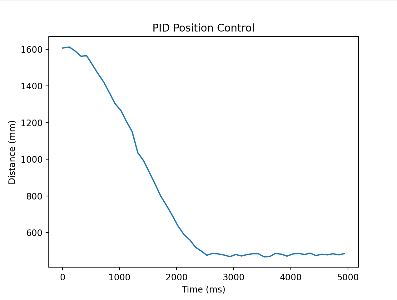 This image has the same parameters as the first video I linked where I only use proportional control. While it reaches steady state with very low oscillation, it also reaches 0 speed which is a problem to ramp back up again.
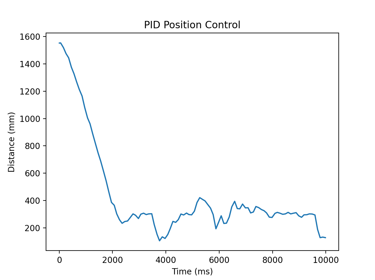 This image uses the proportional and derivative control from the third video. The values oscillate around the steady state a lot more so the gain values are too aggressive.
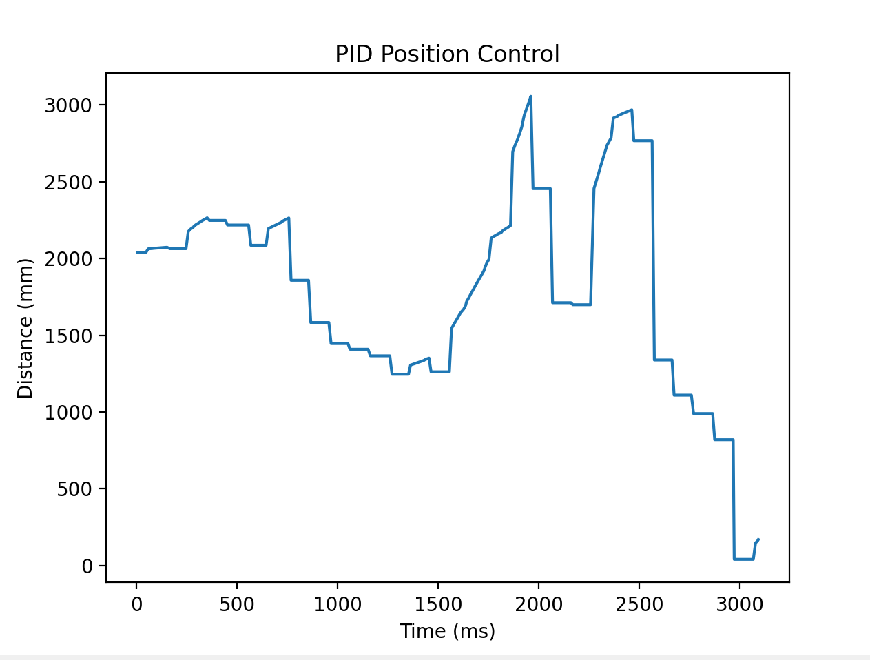 This image corresponds to the parameters in the last two videos. I don’t think the graph corresponds to either video but nevertheless I’m moving the target in front of the car to produce this graph.
Videos


